4.4 On the generator-principle and generator constant
When the pendulum is set in motion the generator principle
comes into action. Movement induces electrical voltage in the coil,
which is greater, the faster the pendulum moves. It is known, that:
Force · Distance = Work = Voltage · Electric Current · Time
is valid. If we re-arrange this we conclude:
![]()
Remember: ![]()
wherein n is the number of the coil's windings; B the value of the magnetic induction; l the length of that part of each wire, seized by the magnetic field.
| Additionally we have for Lorentz' force: |
| Therefore: |  |
So the induced voltage is proportional to velocity, the fraction is a constant. If one then uses the pendulum in an experiment as an ampere balance, as is shown in the following figure:

Fig. 39: Static determination of the generator constant S with an ampere-balance
then one can determine the generator-constant S of the
pendulum by static means. From this the velocity of the pendulum that
corresponds to a given induction-voltage can be calculated as follows:
![]() .
.
The following diagram shows the result of such a measurement for S:

Fig.40: Measurement of the generator constant
For our horizontal seismographs we measured approximately:
S = 250 N/A = 250 Vs/m
There is also the possibility to determine the generator constant dynamically with the help of an Hall-probe. In this case the Hall-probe is attached to the pendulum in the vicinity of the magnet. Firstly one records the Hall-voltage with the help of a precise voltmeter and the corresponding displacement of the pendulum measured accurately by a �m-screw. Then secondly one allows the pendulum without additional damping to swing freely and records simultaneously Hall-voltage and induced voltage within the seismograph's coil. The Hall-voltage signal is recalculated into the matching displacement signal. One differentiates the displacement numerically with an appropriate PC-software and thus receives the velocity of the pendulum in relation to time. The two sets of data from a measurement at the North-South seismograph of our station can be seen in the following diagram.
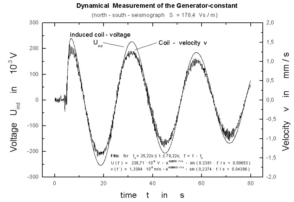
Fig.41: The dynamic determination of the generator constant
The generator-constant S of the
S = n · B · L,
wherein n is the number of the coil's windings; B the
value of the magnetic induction; l the
length of that part of each wire, seized by the magnetic field.
How one can deduce the movement of ground from the voltage signal will be discussed in the following chapter.